 |
Marsico
Hall Microscopes Facility
(MHMF.ORG) |
 |
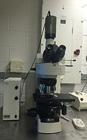
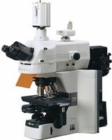
Nikon 80i Upright
Microscope
Introduction:
This upright widefield microscope system is intended for transmitted light
imaging or fluorescence imaging. Transmitted light imaging uses the green
QIclick camera with Windows 10 on the computer called Hamilton. A gray
Hamamatsu OrcaER camera is available for fluorescence using the Windows 7
computer called Farnsworth.
Please feel free to discuss camera capabilities and using the microscope with
personnel.
Book
this scope:
- If you have not been trained or received an orientation session on this scope please
contact personnel.
-
Currently there is a
booking calendar for the Nikon 80i
 -
Those who have booked have priority, then its first come first
served.
 Warnings:
- The liquid light guide is fragile. Please do not bend, kink or over flex the liquid light guide.
It
plugs into the back of the scope body from the Nikon IntensiLight (C-HGFI).
It is prone to damage.
Notes:
- One Ethernet cable is shared between the two computers. Please manually
connect the cable to the appropriate computer in order to be able to logon.
- The 40x 0.95 NA objective correction collar should be dialed to 0.23 for
#1.5 cover (170um) slips.
- A monochrome CCD camera (ErcaER) is available
- Suitable for DAPI/FITC/TxRd/CY5 like fluorescence
- Runs off a separate computer called Farnsworth
- The QIclick camera on the stand will need to be swapped with
Orca ER camera
- The CY5 cube is shared with the Button lab.
The cube projects orange light from the objective. Please arrange with Michael if you need it.
- The Nikon Intensilight C-HGFI fluorescence light source should not be turned on if just transmitted
light imaging is going to be done.
- Leave Nikon Intensilight C-HGFI, metal halide lamp, if used, on for at least 5 minutes before turning to off.
- Room access needs to be arranged.
Powering up:
- (if everything is off)
- Check that the three table legs are floating
- Turn on camera on top of the scope stand (green light on)
- Ensure computer and monitor is powered up (usually left on 24/7)
- Turn on small square blue switch on right side of scope (filter changer power)
- Turn on rocker switch on the back left side of the scope stand (small
green light at front is on)
- Ensure green switch at front of scope is on (incandescent lamp for
transmitted light e.g. H & E)
- Ensure incandescent lamp dial on the front left of the scope is
fully counter-clockwise (clicked position)
- Only turn on Nikon IntesiLight metal halide light source if fluorescence imaging is going
to be performed. (Please turn it off if it is not going to be used)
Setting up for transmitted light imaging
--> If transmitted illumination is not required then go to
"for fluorescence imaging only" below
- For all transmitted light modalities, first set up
Kohler Illumination
- On the right side of the trinocular head set the rod to "Bino &
Photo"
- Polarizer (A) is out
- Fluorescence cube is out (Choose "ND" at 1 or 32) on the somewhat mouse like
control
- Select objective (make sure objective is not going to rotate onto
sample/slide)
- Maximize field iris (F.S. = field stop = diameter of light to
stage))
- Minimize condenser aperture (c) (angle of light to stage is minimum.
Gives max. depth of focus, highest contrast - great
for find sample)
- Focus on sample
- Kohler:
- Set condenser ring to "0" (note blank, "Phase 2", "Phase 3,
"N2", "2-4x")
- Minimize field iris (F.S.)
- Focus condenser (Knob below stage on left) until field diaphragm
is in focus
- Center hole of light
- Open F.S. until hole just fills the field of view as seen
through the eye pieces
- Open condenser aperture to maximum (o)
- Refocus image if necessary
- Kohler illumination has been set up. Will not have to redo
if just changing slides.
- Note: Kohler illumination will have to be redone if objective is
changed.
- If using the 2x or 4x objective set the condenser ring to "2-4x"
-
- For Nomarski (DIC) - only if desired
- Only with objectives labeled "DIC"
- Set up for Kohler as described above
- Slide in Polarizer (push to the left)
- Open condenser aperture maximally
- Select condenser-side Wollaston prism by turning the condenser
turret to N2
- Push in Analyzer
- Rotate upper polarizer for optimum contrast
- For Phase contrast - only if desired
- Set up for Kohler as described above
- Check that the Polarizer (at the trinocular head is out of the light path (to the right)
- Open condenser aperture maximally. IMPORTANT!!! If the
condenser aperture is closed, you will get NO light!
- Select the correct Phase Ring for your objective on the condenser
turret:
-
| Mag |
NA |
|
Feature |
Condenser |
|
Phase |
WD |
| 2x |
0.1 |
PlanApo |
lambda |
2-4x |
|
- |
8.5 mm |
| 4X |
0.13 |
PlanFluor |
|
2-4x |
or |
PhL |
16.5 mm |
| 10X |
0.3 |
|
|
0 |
or |
Ph1 |
4.0 mm |
| 20x |
0.45 |
ELWD |
corr |
0 |
or |
Ph1 |
1.0 mm |
| 40X |
0.75 |
ELWD |
corr |
0 |
or |
Ph2 |
0.14 mm |
| 100x |
1.4 |
|
|
0 |
|
DIC |
0.13 mm |
| 100x |
1.3 |
|
|
0 |
or |
Ph3 |
|
- *The Ph3 objective must be obtained from
a facility director for each use
- Other objectives do not have phase contrast
- Check that the analyzer is out of the light path
- If the contrast is not good:
- Turn the wheel below the eyepieces from "O" to "B"
(for Bertrand lens)
- While looking down the eyepieces, use the little silver knob on
the eyepiece wheel to focus the Bertrand lens on the phase rings
- If the light ring is completely within the dark ring, move the
eyepiece turret back to "O" and continue
- If the light ring is NOT completely within the dark ring:
- Find 2 red-handled Nikon screwdrivers on the left side of
the transmitted light arm
- Insert the screwdrivers into the inner screw holes of the
Phase ring insert in the condenser turret.
- Turn the screwdrivers until the light ring is completely
within the dark ring
Setting up for fluorescence imaging
(only if required)
- Lower objectives
- Pull out analyzer slider on right side of scope trinocular head (above filter cube
carousel)
- Choose required objective. (Generally choose a lower power,
locate sample and region of interest and then move to a higher
power)
- Ensure incandescent lamp is off at the switch on the left side
of the scope OR the green power switch at the front of the base is
off
- Place sample on stage, cover slip up (This is an upright
microscope)
- Choose dichroic filter set by changing the "ND" (yeah this is not
labeled correctly) setting on the mouse like control: 1 or 32=none
2=DAPI 4=fitc (blue
light) 8=tritc/texas red (green light)
16=CY5 (orange light for FarRed)
-
Open fluorescence shutter on Nikon IntersiLight
- Focus on sample
- Switch to higher power objective if desired
Q-Capture - running the camera
- Camera must be on before Q-Capture software is started
- For transmitted light color imaging set the intensity wheel on the left
side of the base of the scope to its maximum counter clockwise clicked
position (ensures consistent color spectrum from the incandescent halogen
lamp)
- Run Q-Capture:
- Press tool/exposure control window
- Press green triangle (live capture)
- Tab 1 set to 8 bits for camera and set to 8 bits for capture
- Adjust exposure
- Select tab 2
- Select rectangular area that has no features
- Press Color Balance button
- Press capture to acquire image
- When saving images turn off live viewing
(avoids corruption of image while saving - due to firewire driver bug)
Powering down
- Turn off the metal halide Lamp switch if it is turned on
- Save captured images
- Exit Q-Capture by hitting the red X on top right of window
- Copy data to USB drive or network share
- Turn off:
- Camera
- Switch at left rear of scope stand
- Blue switch at right of stage
- Transfers images to \\Network-server or USB drive
- Safely eject USB devices of it has been written to
- Log off computer (please do not turn off computer)
- Clean immersion objectives used. Gently blot lens with lens tissue and wipe
surrounding area. Clean up spills on the scope. Please trash
disposables.
Equipment Information
Objectives:
| |
Mag |
NA |
|
Feature |
Condenser |
Phase |
WD |
|
| |
2x |
0.1 |
PlanApo |
lambda |
2-4x |
- |
8.5 mm |
|
| |
4X |
0.13 |
PlanFluor |
|
2-4x |
PhL |
16.5 mm |
|
| |
10X |
0.3 |
Plan Apo |
|
0 |
Ph1 |
4.0 mm |
|
| |
20x |
0.75 |
Plan Apo |
|
0 |
Ph2 |
1.0 mm |
|
| |
40X |
0.75 |
Plan Apo |
corr |
0 |
Ph2 |
0.14 mm |
Correction collar must be set correctly |
| |
100x |
1.4 |
Plan Apo |
|
0 |
DIC |
0.13 mm |
|
| |
100x |
1.3 |
|
|
0 |
Ph3 |
|
Not kept on scope |
- Notes:
- WD = working distance (from bottom of objective to top of cover
slip)
- corr = correction for cover slip thickness (number*10
is thickness in microns)
- 100x 1.4 is not par focal. This objective will have to be
moved closer to sample relative to focus position of other objectives
- 2x 0.1
- 4x 0.13 PhL
- 10x 0.3 Ph1 dl 1.2 mm wd=15.2
- 20x 0.75 wd=1.0
- 40x 0.95 wd=? corr (coverslip correction collar must be setup for
optimal image clarity)
- 100x 1.3 NA DIC/ph3
- * = objective not kept on the microscope stand. See a
facility director if you require this objective.
 Camera:
Filters:
- On Microscope carousel
- FITC - blue excitation/green emission
- Rhodamine / Texas Red - green excitation/red emission
- Dapi - UV excitation/blue emission
- CY5 - red excitation/far red emission invisible by eye (on loan from Brian)
Computer:
 Warnings:
 Camera: